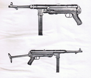
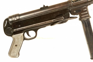
MP40
Introduction
The story of the MP40 is one of a continuous process of manufacturing simplification in order to save production time and expensive and critical tooling costs. The MP40 is in fact a simplified MP38. It was never the idea to create a complete new model. Most parts of the MP40 were modified during its four years of production. I feel that, from a design perspective, the MP38 is far more interesting than the MP40 however the MP40 is from a production perspective far more interesting. Basically the production methods of the MP40 were revolutionary in the arms industry. Never before subcontractors were used at such a large scale as with the production of the MP40. Apart from this revolutionary production concept also the methods of production changed dramatically. Where the larger parts of the MP38 consisted completely of machined parts the larger parts of the MP40 only had the barrel and the bold machined.
Cooperation between factories
Even before the start of the war it was clear that both Erma and Haenel could not meet the high demand the Wehrmacht required. In fact they even could not meet the production targets they planned themselves. Apart from production problems and delivery problems with subcontractors Erma and Haenel were basically too small to meet the demand. Already in 1939 it was clear to the Heeres Waffen Amt that something needed to happen quickly, both on the method of production as well as the production capacity.
I think that in this early stage both Erma and Haenel worked closely together. There are various examples that this was the case. For example very early MP38 magazines have both the 280(Erma) Wafffenamt stamp and the 37 (Haenel) waffenamt stamp. Also it's frequently seen that on number matching MP38's (Erma) small parts like the strap loop had a different waffenamt code (37). Apart from this kind of proof it's obvious that engineers and designers from the Erma factory would have trained and helped out the Haenel personnel with the producton start up of the MP38. As I described on the introduction page, Hugo Schmeisser role should not be underestimated in this cooperation. Already the Heeres Waffen Amt had more or less forced Erma to use Schmeisser’s patented designs in the MP38. Also the first factory after Erma that started producing the MP38 was Haenel. Designers of both companies together with the “mass production” specialists from Merz Werke and Krupp developed the “mass production” version of the MP38. Apart from improved production methods something also needed to be done about the production capacity. Steyr was asked to assist in the MP40 production. Steyr never produced the MP38 although some books claim they did! Steyr did however produce the MP40 and was also reponsible for the highest production numbers during the time the MP40 was produced.
MP40 Modifications
I consider the modifications and changes between the MP38 and the MP40 and later between MP40’s as the most interesting part of the history of these weapons. Some books refer to different versions of the MP40 but I think this is not a realistic way of describing the MP40. Partly it might be true especially if you think about the late 43 and 44 Steyr "types" but there is definitely no way you can describe the earlier modifications as "types" in my opinion since this has been a gradual production impovement which started already with the MP38. Also I don’t think the manufacturers had different versions in mind when they modified the MP40. In fact these so called versions don’t have any military status. Apart from the MP40-I (double magazine type). One book refers to 5 versions, the other to 7 versions. In order to give a good description of the alterations and simplifications I think it's best to do this by describing the modifications per part.
I will describe the modification as per main part. These parts are:
1) Grip section & lower receiver
2) Receiver including the magazine receiver
3) The bolt & mainspring
4) Barrel
I will also include the differences with the original model the MP38.
1) Grip Section
1.1 Grip:
The grip section comes in 4 different types:
1) The aluminum MP38 grip. Produced from 1938 till 1941 by Erma and Haenel (See the picture top left)
2) The simplified sheet metal MP40 "open" grip with ridge around the triggerguard. The grip consisted out of two halves stamped together. Produced by Steyr (660 or BNZ), Erma (27 or AYF), Haenel (122 or FXO), Merz Werke (COS) and National Krupp Registrier kassen (CND). Produced from 1939 until 1944.
3) A further simplified sheet metal, one piece grip. Slightly thicker and no ridge around the triggerguard. This grip was produced by Steyr as of late 1942 until 1943.
4) An even further simplified handgrip. Here the grip has been permanently welded together with the lower receiver. The ridge is back around the triggerguard and a metal band is welded all over the grip, triggerguard and the back end of the receiver.
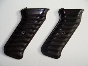
1.2 Grip plates
At first glance the grip plates of the MP40 and MP38 look very similar. If you take a closer look you can see there is a slight differrence in shape. If you disassemble the grips and turn them around you can see that there is a big difference in shape. The MP38 grip plates have small bulges that fall exactly in place with the holes in the aluminum machined handgrip. With the MP40 it's just the other way around. Here the grip plates have molded holes where the metal bulges from the sheet metal handgrip fit exactly into. The grip plates are made of Bakelit or to be precise "Margolit". The grip plates and the foregrip were produced by two suppliers as far as I know at this moment. This was the Vereinigte Isolatorenwerke A.G. or Viacowerke (the secret code was "gbm") from Berlin-Pankow and the "Allgemeine Elektrizitätsgesellschaft which from Henningsdorf". The last one is the in Europe well know electrical appliances company: AEG./Elektrolux.
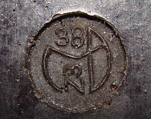
The "Materialprüfungsamt" logo
In December 1938 the Materialprüfungsamt (Material Proofing House) from Berlin Dalhem developed a logo or stamp for the companies that were involved in the production of Bakelite. As well known to most German Militaria collectors the German National Socialistic Government agreed on a law in July 1939 that all small arms factories and their sub-contractors had to carry a numerical code. This was done to make it more difficult for the enemy to trace back the factories and maybe bomb them. At the beginning of 1940 it was changed to a 3 letter code. The logo, as you can see in the picture, is a combination of the letter "M" and "P" which stands for "M"aterial "P"rüfung. Then there is the "Z3" code which was the materialcode for "Carbolic Resin (Bakelite) with a woodpulp filler" type 3. On the grip plates of "Viacowerke" there is an extra stamp with the "gbm" code. The "materialprüfung" code is does not contain a number code and remains empty. The handgrips produced by AEG had a small "38" code in the logo and no separate code. You see these codes back in the Bakelit foregrip which I will discuss later. Please let me know if you think there should be another factory credited. At this moment I think there were 2 as described in the previous paragraph.
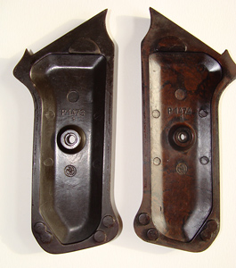
The MP38 grip plates are numbered as follows:
- Left grip plate: P1473 1 and below the screw hole there is the "materialprüfungsamt" logo/stamp.
- Right grip plate: P1474 1 and again the "materialprüfungsamt" stamp/logo
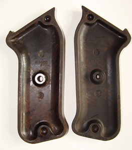
For the MP40 there are 2 different Bakelit (or "Margolit" as was the trade name of Viacowerke for Bakelit) grip plates as far as I know at this moment. (I'm not talking about the different colors). The first version of a pair of MP40 grip plates shows:
-Left grip plate P1488 2 and the "materialprüfungsamt" logo with the small "38". Which means it was produced by AEG
-Right grip plate P1489 3 and again the "materialprüfungsamt" logo
Please note that the grip plates in the pictures have the corners sawn off. This is not a production difference!
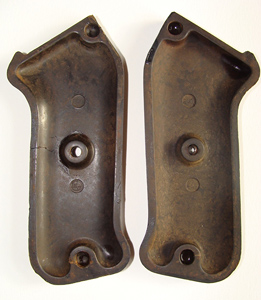
With the second version, both the right and left grip plate show only the secret company code "gbm" and again the "materialprüfungsamt" logo but then without a numerical code in it. This because the code gbm was already pressed into the Bakelite.
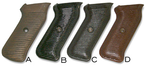
The Bakelite handgrips (as well as the foregrips) came in different colors. Especially the red Bakelite Grips are very rare. It seems that these red Bakelite Grips were randomly produced. In my Serial Number List section I only have 3 MP40 with red grips. 2 at the end of 1943 produced by Erma and 1 made at Haenel early 1941. Maybe these color variations are due to differences in the production process or variations in the raw material.
Supposedly a few different wooden version of the handgrips were made. I haven't been able to substantiate this. They could be "field expediant" repairs or manufacture, or post war issue.Though a wooden handgrip was also produced for the MP44. I haven't seen enough of these to convince me that these were official production for the MP40. Same with the aluminum handgrip. I think that this is also a post war, one of a kind, version.
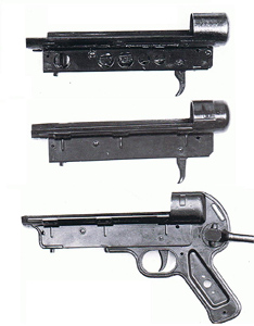
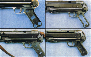
1.3 Lower receiver:
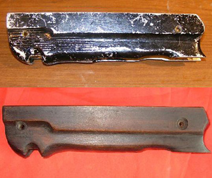
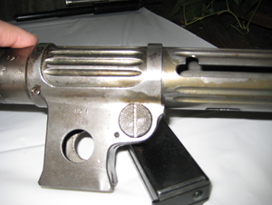
The lower receiver is in fact the most important constructual part of the MP40. This part is responsible for holding the receiver and the grip section together. Also it houses the trigger group. From a production standpoint this part is really pre-eminently the realization of the new production methods (die stamping) developed by the, at that time, high-tech German war industry. At first glance from the side there are not really any differences in design apart from the grip section that is welded to the lower receiver in the later models. However if you look from above (see picture) you see that there are a lot of differences between the MP38 and MP40 lower receiver. Where the MP38 exist out of 2 massive steel plates (excluding the end cap), the lower receiver of the MP40 exists out of at least 5 different stamped sheet plates, excluding the end cap. The sheet metal of the MP38 is also a lot thicker than the MP40 plates. In order to reduce weight with the bottom plate of the MP38 receiver, holes were milled in the sides.
1.4 Foregrip:
As well as there is a slight difference in shape between the grip plates of the MP38 and MP40 there is also a small difference between the two foregrips. The reason why the designers had to change the shape of the original Bakelit foregrip a little bit was a result of the changed dimensions of handgrip. The MP38 did not have a ridge around the triggerguard. The out of a metal sheet stamped grip from the MP40 did have this feature. In order to make the Bakelit foregrip fit a slight change had to be made. This is best explained by a picture (see right). An MP38 Bakelit foregrip would not fit an MP40. However there is one exception. As explained under 1.1 Steyr produced a simplified handgrip without the "scalloped out" ridge around the triggerguard. They did not go back to the "old style" MP38 Bakelit foregrip although this would have looked better from an esthetical view, but I don't think they worried about this during the war especially since the other factories were still producing the handgrip with the ridge. I think the MP38 foregrip would fit the Steyr version from 1942/1943 but I'm not sure since the inside also shows differences. Like the grip plates the foregrip comes in several colors. Initially production started with the blended brown Margolite foregrips on the MP38. These foregrips seem to be slightly lighter of colour then the later MP40 foregrips. Later we see the more straighter dark brown foregrips and the almost black foregrips. Most rare are the red Bakelit foregrips. We see these sometimes on Erma 1943 MP40's.
When comparing the inside of the MP38 Bakelit foregrip with the one from the MP40 there are also some small differences. First off course there are again the different codes and markings.
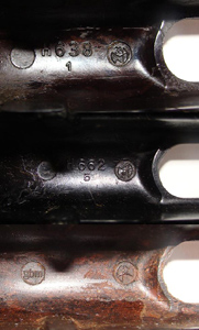
On the pictures that I received (left) I see 3 different versions:
1) H638 1 with the materialprüfungsamt logo 38-z3 (AEG) MP38
2) H662 5 with the materialprüfungsamt logo 38-z3 (AEG) MP40
3) gbm coded with materialprüfungsamt (Viacowerke) MP40
Please check the section grip plates for more information on the materialprüfungsamt logo. I'm pretty sure there are foregrips with different markings. It's difficult to get more information on this since the problem is that the foregrip is screwed to the lower receiver. Also the retaining pin of the "take-down"/breech pin needs to be disassembled knop of the breech pin needs to be removed. I know that most collectors are not fond of disassembling, to this extent, their original firearms. Please let me know if you have some more markings or codes of the different Bakelit parts. info@mp40.nl
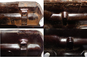
Apart from the outside design and the markings the inside design of the MP38 and MP40 are also different: These diffences are again also better explained by a picture. On the top you see a Viacowerke (gbm) MP40 inside Foregrip. On the bottom it's the inside of a AEG (38) MP38 bakelit foregrip. In order to adapt to the new MP40 lower receiver these small changes needed to be made.
Every once and a while aluminum or wooden foregrips are being sold on different auction websites. The aluminum foregrips are definitely not manufactured and used during the second world war since aluminum was considered a very scarce strategic material. After the start of the second world war aluminum was almost exclusively used by the airplane industry.
This is also the reason why they shifted from material when they started producing the MP40. The aluminum foregrips are post war and were made by the French. France used the MP40 for their troops in the fifties and early sixties (for example in the Indo China/Vietnam war). At that point in time it was more ecomomical to manufacture these foregrips with aluminum. I also have seen one or two wooden foregrips. I do not think these are military issue. It would be too time consuming and therefore too expensive to manufacture during the second world war. Bakelite however was very easy and quickly to produce. I think the wooden foregrip was made by a someone who needed to replace a broken bakelite foregrip and could not care less about the originality of the gun.
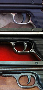
1.5 Trigger Assembly
As far as I know there are no real differences in the trigger assembly. The only thing I can think of are the different shapes of the trigger as you can see in the picture in the lower receiver section. Some trigger assemblies are coded. I received one picture with the code "kur" stamped on it. The code "kur" was stamped on parts like the barrel and thus the trigger assembly. What I would like to know if the "kur" code is also seen in Haenel and Erma MP40's? The code "kur" stands for "Steyr Daimler Puch AG. Werk Graz, Fuhrhofgasse 44" in the big "Code Book" but production took place in a production facility in Warsaw in Poland.
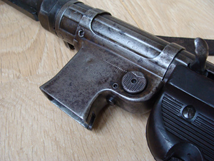
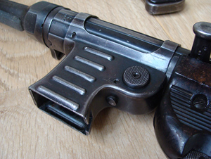
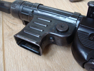
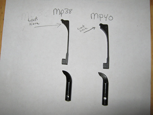
1.6 Folding Stock
Only recently I learned that there are different folding stocks. I got to learn this by from Eddie B. who has send me an enormous amount of pictures with production differences between the MP38 and the MP40. As you can see from the pictures there is a slight difference. The braces of the early MP38 folding stock are machined in a finer way than the later braces. Also the tubes seem to be machined although I'm not sure of this. It's not a strict difference between the MP38 and the MP40. The MP38 that is shown in the picture is a rare Haenel, 122 coded MP38. It could be that at that early time Haenel produced the folding stock in a slightly different way than Erma did. This is just an assumption because I base this conclusion on only a single sample MP38. It could also have been that this was one of the many small production simplifications. The folding stock mechanisme is known to wear out. I've heard of many MP38's and 40's where this problem is the case.
.jpg)
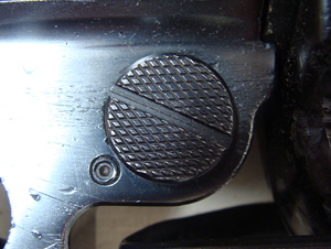
There were also production variations in the push-button and cam for the folding stock. “Standard” push-buttons and cams had “teeth” machined into them for engaging a closed / open position.Later production variants did away with the “teeth.” See an exemple of this to the right.
2 The receiver
2.1 The receiver tube
The design of the receiver in combination with the magazine receiver comes directly from the MP18. This part of the MP38/40/41 can be fully credited to Hugo Schmeisser as the patents proof. Although the system used in the Erma EMP and the EMP36 are to some extent similar, in detail there are a lot of differences. Hugo Schmeisser influence in the German arms industry must have been significant since Erma changed from the EMP system to the Schmeisser system.
Both the receivers from the MP38 as well as the MP40 consist out of two parts. First the tube itself and secondly the barrel bushing. This barrel bushing is responsible for connecting the tube to the barrel. The receiver of the MP38 is a fully machined tube. The production of this part was very time consuming. The MP38 tube is really beautifully made but must have taken ages to make. Especially the grooves over the full length took some time to machine. These grooves were machined in order to make the MP38 slightly lighter. In fact here is where the first change took place. Initially the grooves were running over the full length of the receiver as we can see on the picture next to this text.
This MP38 must have been some sort of prototype since we only see this version in the first manual from 1938. The designer quickly recognized that the construction was not stable enough. The magazine receiver was probably not strongly enough connected to the tube. Instead of the easier to produce grooves over the full length of the tube they now had to make the production process more complex because of the constructional strength of the receiver and magazine receiver. As described earlier in 1939 the design of the MP38 was completely reviewed and adapted for the new mass production techniques. The fully machined tube was replaced by a stamped, rolled up and seam-welded metal sheet.
Early MP38’s had a concave base to the rear sight assembly while the later MP38’s had a “square-ish” base to the rear sight! Another advantage of the MP40 receiver internally was that it allowed for collection of some debris in the “heights” of the inner tube wall, as well as less friction from the bolt sliding down the receiver tube as in the MP38.
Without the proto types the receiver comes in 2 versions.
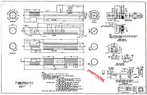
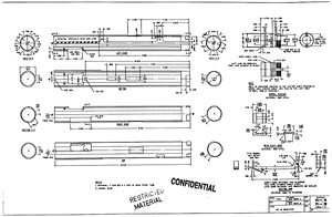
-The MP38 milled receiver mp38 (Download Post war top secret PDF drawing of MP38 tube)
-The MP40 stamped sheet metal receiver.mp40 (Download Post war top secret PDF drawing of MP40)
With the implementation of the two piece safety retracting handle the receiver had to be adapted post-production in the military arms repair depots. This was done by grinding a notch in the front part of the handle slot of the receiver. This usually was done by the Waffenmeister. On July 25th 1942 an order was issued to replace all old retracting handles with the new safety retracting handle. The complete adaption was to be executed before the 20th of May 1943. Unofficially these MP38's and MP40's were called the "gemischt" (mixed) model. So apart from these "field adaptations" the newly produced MP40 receivers also had this notch as part of the modified manufacturing stamping dies from mid 1942.
Another difference relates to a simplification in production. At first the barrel bushing was brazed to the receiver tube. In order to simplify the production process, the barrel bushing was crimped to the receiver tube. This was only done with MP40 tubes since these tubes were made of sheet metal. As far as I know the majority of 1942 and 1943 receiver tubes are crimbed. I don't know if this production method was the new way of production or that it was "in between" production method. I also don't know which factory was responsible for this change in production but it would not surprise me if it was Steyr. Most production simplifications were initiated by Steyr. Any additional information regarding this subject would be very welcome. info@mp40.nl
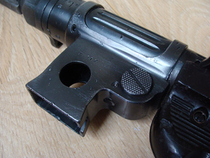
2.2 The magazine receiver:
The magazine receiver used on the MP38, 40 and 41 is a direct copy of the by Hugo Schmeisser designed and patented MP18.1 (verbessert) magazine receiver. Instead of using the magazine receiver on the Erma EMP and the (prototype) EMP36, Erma was more or less forced to use the Schmeisser design. This is clearly a proof of Hugo & Hans Schmeisser's influence on the "Heerswaffenamt". The double feed magazine design used on the Erma EMP (and before that the Bergmann MP34/1 & MP35/1) was in fact a better system and would have caused lesser stoppages. Hans and Hugo Schmeisser were very smart businessmen and knew off course that if their patented feeding system was choosen they would make a fortune with the future military contracts. Roughly a 900.000 MP's were made and about 12 million magazines. The income generated by the Schmeisser brothers from the licensees must have been substantial.
The designers must have been impressed by the work of the American Thompson designers with regard to the placement of the magazine. It also could have been a feature that was requested by the military like the folding stock and the barrel resting bar. On all German "Maschinenpistolen" designs from the MP18 till the EMP the magazine was always designed on the left or the right side of the receiver tube. When shooting a Submachine gun the gun alway "climbs" as a result of the recoil. With the older designs where the magazine feeding system came from the side there was another problem. Apart from the "climbing" problem the Submachinegun also tend to move sideways when holded as a result of the weight. The designers of the M1928 Thompson must solved both problems (more or less) by placing the feeding system under the receiver tube. The MP38 does indeed shoot very stable compared to other Sub machine guns of that era. The negative side of having the vertical magazine housing was that a soldier would have more trouble to fire from a prone position.
The magazine receiver comes basically in 4 different versions.
1) The MP38 version with the drilled weight saving hole.
2) The early MP40 smooth version.
3) The improved "ribbed" version with square grinded notch.
4) The improved "ribbed" version without square grinded notch.
Please find the pictures below:
Production simplification is again the cause of the different versions. The MP38 magazine receiver was fully machined and of extreme high, pre-war, quality. This MP38 magazine receiver was of course pretty heavy since it was machined out of one piece of metal. In order to make it slightly lighter a hole was drilled in the sides. To meet the high demand simpification was necessary so the designers came up with the second version for the new MP40. This second version consisted out of two pressed sheet metal plates (not counting the push pin and the magazine catch). Since the metal sheet version weighted already al lot less than the old MP38 magazine receiver there was no need for a hole.Often this type of magazine receiver has the last three digits of the serialnumber on it. Some confusion might arise here since the "Kriegsmarine" also stamped an inventory number on it. Late 1941 a third version was designed. This one is the most common. This version had 5 longitudinal ribs pressed in the sides of the housing. Main reasons why these changes were implemented are:
1) The most important reason was adding strength to the magazine receiver, the smooth version could be easier damaged.
2) On the inside of the early MP40 version dust and dirt could obstruct the magazine from entering the magazine receiver. The later version with the longitudinal grooves offered some space on the inside for dirt to move in to.
3) The new magazine receiver offered the shooter a better grip.
The fourth version is almost exactly like the third but does not have a grinded square notch on the back side of the magazine receiver. To be honest I really do not have a clue why this notch was grinded out in the first place and secondly why it was not necessary anymore with the later magazine reciever types? I have put out this question to Rich U. since he has a lot of "hands-on" experience with the MP40. He came back to me with the following possibilities:
1. It is directly below the ejector... perhaps it has something to do with placement of the ejector?
2. It may be an alignment slot for the centering of the mag housing (with the take down slot on base of the receiver) onto the receiver when initial building?
3. Possible difference in magazine well size to take the "special" MP40 magazines I have seen...
4. It may have been a re-inforcing slot to allow for a special tool to fit and turn the mag housing onto the receiver without damage to the mag well!! The tool would look like a MP40 magazine, but would have an additional metal flange on back to allow for turning the mag housing. Or..........
5. With the special tool in a jig made to hold the MP40 receiver and the steadying of the mag well... when It came time to remove the barrel, the MP40 mag well would act as a secure block to assist in the un-screwing of the muzzle nut! Having had to remove and install MP40 barrels... this would be a real plus having a tool like that... otherwise, one has to use an MP40 mag or tool in the housing and risk bending the housing!
According to Rich R. nr. 5 would seem most plausible. To me Nr.1 seems most logical. Please let me know if you have any suggestions here at: info@mp40.nl
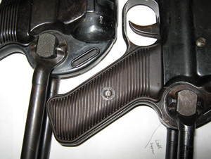
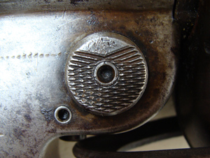
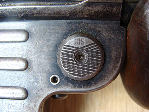
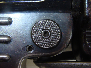
On the 4 pictures below you can also see 4 different versions (as far as I know) of the push button to release the magazine.
1) First the MP38 machined larger push button
2) The MP40 machined push button with one small triangular part of the surface left unworked
3) The MP40/MP41 machined push button with the "cos" Merz Werke code stamped on it.
4) The MP40 machined push button with completely reworked surface.
Please let me know if you know of other versions: info@mp40.nl
Another small internal change was made on the ejector. The ejector in the MP38 was a lighter and smaller one then the new one used in the MP40. This was done because during the first exercises and later the combat experiences in Poland it happened frequently that the ejector broke. So a new stronger and slightly longer one was designed, tested and used in the newly designed magazine receiver of the MP40. The fact that it was longer is important to mention. When the ejector broke the soldier had a massive problem because the gun could not fire anymore and would jam. This is a soldiers nightmare! Secondly when you would survive a close combat fight you needed to bring the broken MP38 to the Companies Waffenmeister. He would face the second problem. Since the ejector was so short it was very dificult to remove it. All these problems were feeded back to the designers. They made the new ejector stronger but like I said also longer so that it would stick out a little at the bottom of the magazine receiver. When the ejector needed to be removed it was now easily removed by a nail puller or some other tool. I don't know if there are still any MP38's out there which received a new "mp40 ejector". If you have any more information about this then please let me know. info@mp40.nl
2.3 Backsight
3 Barrel Section
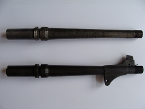
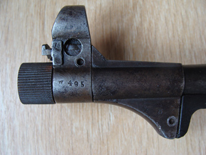
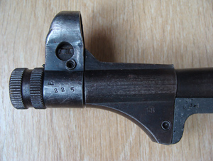
3.1 The muzzle
The muzzle itself without the subparts is one of the few parts of the MP40 that did not undergo a simplification. In fact the MP40 muzzle is exactly the same as the one used on the MP38. Biggest difference is the finish. The finish of the MP38 muzzle is of outstanding pre-war quality and has a beautiful polished look. Quality of the finish decreased during the war years. The quality of the steel remained however very good.
The following production codes can be found on the barrel:
Kur = Steyr Daimler Puch A.G.
ar = Mauser Werke. Berlin-Borsigwald (often with a "bnz 1" stamp)
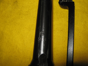
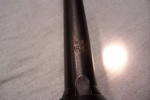
Furthermore a steel "sample number" or "lot number" can be found stamped in the barrel. This code is sometimes confused with a serial number. Some collectors thought their MP40 was not numbermatching because this "steelstamp" did not match the serial numbers. This number can sometimes be found under the barrel protector.
All the subparts can be fairly easy stripped down apart from the front sight holder. This is soldered on to the muzzle. It can be removed by heating it. Since the barrel section consists out of numerous parts I don't want to describe the difference between complete barrel sections. Instead I will describe the variation in subparts.
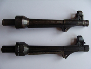
3.2 Collar nut
The collar nut is the part that connect the barrelsection with the receiver tube. The muzzle nut holds the 2 split rings or "half moon" rings. These split rings are there to hold the barrel in position so it cannot move forward or backward. This connection is fairly unique in the world of small arms in my opinion. The muzzle protector holds the muzzle nut on it's place when unscrewed from the receiver tube. Without it one would loose quickly the split rings.
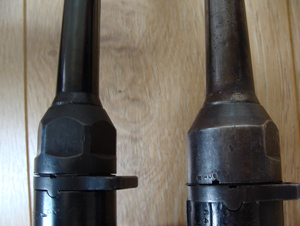
There are basically 2 different versions of the collar nut:
-the six sided version
-the simplified 2 sided version.
The 2 sided simplified version is quite rare and sofar I only registrated them on number matched Erma (ayf) and Steyr (bnz) MP40's built in 1943 and 1944.
3.3 Muzzle protector/Barrel rest
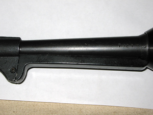
The barrel rest was a new feature that probably was added after the first trials with the MP36 as the MP36 did not have this feature. I think in the period 1936 till 1938 it became clearer that thenext war was going to be mechanized and that a new kind of soldier named "Panzer Grenadier" would fight from armored vehicles as this fitted in the new Blitzkrieg doctrine.
In these armored vehicles, the Panzer Grenadier would often be armed with sub-machineguns. Already on the MP36 there was a hook located under the barrel that prevented the sub-machinegun from accidentally pulling in during firing
Apparently, the "Heereswaffenamt" was not yet convinced about the safety of MP36 bolt. When a sudden jolt from the hard metal of the steel barrel contacting the hard metal of the armored vehicle a shock could be generated, the MP36 could then still bounce back into the vehicle when fired, because of this concern, the engineers from Erma invented a "shock absorber" of sorts, a softer material that could absorb the bouncing when firing the MP36. This "shock absorber” was later integrated in the design of the MP38. Apart from this shock absorbing function the designers gave it a second function. The barrel rest had to prevent the collar nut from unscrewing from the receiver nut, sliding backwards and then releasing the 2 half rings inside the collar nut, thereby changing the headspacing of the bolt to the barrels chamber.
Apparently the Bakelite barrel protector frequently broke, since the "Oberkommando des Heeres" later issued a message in the "Von der Front fur die Front" on the 2nd of August 1944 that broken barrel protectors could be replaced by a hard wood version. This was then to be made by the "Waffenmeister". This message was submitted by Feldwebel Bemme.
The text says:
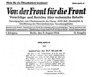
Barrel rest of the M.P.38 and 40
Often the barrel rests of the in the bataillon available M.P.38 and 40 are broken away. When a new one is not at hand I have tried to have them made from hard wood which is possible to make in a few minutes by any troops weapons specialist. These barrel rests have proofed to be good, I can recommend this method to every comrade. The barrel rest is ususlly made from plastic. Bemme, Fw.i.W., Feldpostnumber 44938 A.
To be honest I think that many soldiers left the MP40 as it was. I have seen a few pictures from that time with MP40's without the barrel protector on it. These days you hardly see MP40 without the barrel rest. Very good reproductions and hard to ditinguish from real ones are available made from the exact same material.
The barrel rest has been produced from 5 different materials:
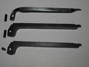
1) Aluminum; mainly used on the MP38 and very early MP40's. As mentioned earlier Aluminum was a scarce material and almost all of it was used in the production of airplanes.
2) Bakelit; most of the barrel protectors were produced form this material
3) Cast zinc; hard to distinguish form the Bakelit ones
4) Sheet metal; late MP40's had this version of the barrel rest. It was very cheap to produce and was issued almost at the same time as the 2 side barrel nut. Most sheet metal barrel rests have a Waffenamt number and a part of the serial number stamped on it.
5) Hard wood; only used for repairs by the Waffenmeister as described
The barrel protector proved to be an unnecessary invention since we have not seen it back on any other sub machinegun after the MP40. Hugo Schmeisser already decided not to use it on the MP41 although this sub machinegun had a different function and was not meant for armoured vehicles and paratroopers.
3.4 Front sight guard
The front sight guard used on the MP38 and MP40 is typically a military suggested feature. Again a proof that the engineers of ERMA were advised by the military after developing the MP36. Most of the German sub-machine guns did not have this feature, including the MP36. The only sub-machine gun that used a front sight protector was the MP34ö. This was probably directly copied from the in 1908 adopted K98a by the German cavalry. This is where we see front sight guard the first time. The ones on the early K98a and the MP34ö were open. The ones used on the MP38 and MP40 were completely closed. Again production simplification was the reason here.
The front sight guard comes in 2 different versions (see below). The early ones has a connector for the hinged muzzle cap. Since this overly complicated accessory was not used anymore after 2 years, the designer removed this from the front sight guard. Most MP38's should have this connector. If not the barrel or the front sight guard probably has been changed over the course of time. On MP40's however this feature is quite rare.
4 The internal parts
4.1 The bolt
The MP40 fires from an open bolt, which means that prior to firing, the bolt is held to the rear by the trigger sear against pressure from the recoil telescope spring. When the trigger is pulled, the sear frees the bolt to go forward under pressure of the recoil spring. As the bolt, with its firing pin projecting from the front of the bolt face, moves forward, it strips the topmost cartridge from the magazine, pushing the round into the chamber of the barrel. The front of the brass 9mm case will be fully seated when it comes to rest against the rim inside the barrel chamber, however, a micro-second before the round is fully seated, the protruding firing pin detonates the primer of the 9mm round and initiates the chemical reaction of the gun powder to fire the round. Some argue that the bolt does not fully seat the round into the chamber before detonation occurs! Note: Minor differences of the rate of fire, and reliability, have been recorded with those weapons that utilized a “fixed firing pin” machined onto the bolt face (like the STEN) and those machine pistols that had a separate firing pin / spring loaded recoil assembly.
As the propellant gasses expand, they operate on both the bullet, forcing it through the barrel and out the muzzle, and in the opposite direction against the bolt, forcing the bolt to recoil backwards to the rear against the pressure of the recoil spring. Since the bolt is about a hundred times more massive than the bullet, it moves much more slowly. In fact, by the time the bullet has left the barrel, the breech has not moved to the rear far enough to fully withdraw the fired case from the chamber. The bolt continues to recoil to the rear, while extracting and ejecting the fired shell to the right and out the ejection port. The bolt assembly continues its rear-ward travel. At this point, if the trigger is still pulled back, the bolt will continue to move forward under the telescope spring pressure, repeating the cycle.
.jpg)
Since the development of the bolt for the MP18 by Louis Schmeisser there has been very little change in the design of the bolt. The MP38/40 bolt is clearly an offspring of the patented Schmeisser designed bolt. The MP18 bolt is very similar to the later MP40 bolt. As described earlier in 1937, the “Heereswaffenamt” must have decided to use the system of Hugo Schmeisser and not the system of Vollmer as used in the Erma EMP or EMP36. An unfortunate choice in my opinion since the single feeding system of Schmeisser would prove to cause so many problems in the future.
Basically there are 5 versions of the MP bolt:
1) The basic MP38 and early MP40 bolt. This type has the early one piece / “hook-type” retracting handle. The retracting handles may have slight differences in contour as they were all hand crafted.
2) The new improved MP40 bolt with the 2 piece safety retracting handle. I estimate that production of these new bolts started in April/May 1942.
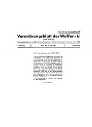
3) On the 21st of August an order was issued in the “Allgemeine Heeresmitteilungen” to replace all old style retracting handles (the hook type) with the new two-piece safety retracting handle (See PDF below left). This operation was supposed to be finished before May 20th 1943. Apparently not all MP’s were adapted since on the first of June 1943 another technical publication order was issued to replace immediately the old retracting handle. The organization responsible for this order’s issue was apparently an even bigger mess at the Waffen-SS, since they again issued on the 15th of July 1944 another order to have the old retracting handle replaced by September the 1st 1944. (see PDF below right) All of the newer replacement two-piece retracting handles were produced by Haenel and bear the eagle over 37 Waffenamt code. Another way of recognizing an improved bolt is by the grinding marks on the inside of the bolt.
.jpg)
4) The MP41 Bolt. This bolt is suitable for semi-automatic firing. The difference with the standard MP40 bolt is that on the bottom side there is a ridge over the full length of the bolt on the right side.
5) The last version of the MP40 bolt is the bolt with the fixed firing pin. In the last phase of the war some experimenting was done with a fixed firing pin machined onto the face of the bolt. The regular telescoping recoil spring assembly was replaced by a shortened MG42 recoil spring. MP40’s that utilized this later version bolt tended to have a very high cyclic rate. Note: These bolts are not to be confused with the Portuguese FDP bolts which have also a fixed firing pin and very similar telescoping recoil spring assembly as the MP40, but without the firing pin pinned to the front. This FDP bolt and telescope spring assembly will fit an MP40, but typically, after firing 5 to 10 cartridges it may jam in operation because the telescoping spring often is too weak. I think the German weapon developers realized this as well and therefore replaced it with a (cut) MG42 spring. In some books it’s stated that the use of MG42 springs was done because there were no telescope springs available. I think it’s just another step in the production development of the MP40 to make production as cheap as possible probably again executed by Steyr.
.jpg)
![]()
4.2 The extractor
The extractor is responsible for pulling out the fired cartridge shell after the bullet has left the barrel. The extractor is fitted into a machined grooved slot on the right side of the MP40. Most MP40 bolts have a hole drilled across through most of the MP40 bolt bodies, this hole is there to assist the armorer in removing a damaged extractor from the bolt head. The extractor is very easy to replace, and is one of the parts that can wear out or break when the weapon is frequently used. This repair work was usually done by the “Waffenmeister” though if necessary it could be done by the soldier himself.
There are 2 different versions of the extractor. The early version mainly used in the MP38 and later reinforced extractor. Probably due to the problem of frequent breaking.
4.3 Telescope spring
The telescope spring is probably one of the most interesting parts of the MP40 family of submachine guns. Not so much interesting because of the legacy it has on firearms in general, after all, the telescope spring has not been used in any other well known submachine gun after World War 2, but more in terms of the invention itself and who was responsible for the invention. In most post war literature the invention has been awarded to Heinrich Vollmer but as a big Schmeisser supporter I have my doubts with these publications although I must admit that I cannot prove the contrary so far.
.jpg)
To me the most important proof that Hans and Hugo Schmeisser were the first (claimed) original inventors of the telescope spring is the patent of the 18th March 1926. Already back then this patent claimed the invention of an entire Submachine-gun which include a telescope mainspring. This patent (Patentschrift 475914**) is a German patent which also proves that already in 1926 the Germans were developing submachine guns, apparently without any secrecy around it towards the only eight year old “Versailles Treaty”. After all a patent is a public document. I think the problem with this patent is that it does not claim the single telescope spring as an invention but a sub machine gun which includes this invention.
Heinrich Vollmer’s Patent of the 29th of June 1933 is not really a patent on a Telescope Spring but on some sort of “breaking”/”stopping” thread that made sure that the separate tubes of the telescope spring could not disintegrate when the telescope spring was pulled out of the receiver.
.jpg)
So both inventors were already developing telescope springs. Because of the German patent 475914 I feel that Hugo Schmeisser invented it first. He probably underestimated the future value of this invention since he used a further development of the telescope spring again in his MKB36 or M.K.36 III. If you check the picture to the righ you see an almost identical bolt and telescope spring as used in the MP38/40/41.
According to Dr. Norbert Moczarski’s “Hugo Schmeisser – zwischen Tabu und Legende“ Hugo Schmeisser had to stop the development of the MKB36 because Erma already patented the telescope spring. To me, it’s still a mystery why the bolt and the telescope spring of the MKB36 resemble the bolt and the telescope spring of the MP38 almost 100%? (also check the form and shape of the magazine!)
According to Lidschun & Wollert’s "Enzyklopädie der Infanteriewaffen 1918 bis 1945" Hugo Schmeisser sued Erma in 1941 while not as much is written that Erma sued Hugo Schmeisser! While Hugo Schmeisser lost the case at the Berlin Court (Berliner Kammergericht), according to Lidschun & Wollert , Hugo Schmeisser but was still allowed to use the bolt and the telescope spring combination in the MP41 which was produced only by Haenel!
I feel that Hugo Schmeisser had a legitimate claim that he was experimenting with the telescope spring for years and he wanted to be declared the inventor of the telescope spring. The main reason going to court was of course money. The Schmeisser brothers were smart businessmen, and due to the military success of the Wehrmacht at the beginning of WW2 and the ensuing massive production run of the MP40, and the future expected needs of greater production growth, Hugo Schmeisser wanted to try to get his fair share.
.jpg)
There are 3 types of the telescope springs:
1) The MP38 version. (probably also used in very early MP40’s)
2) The MP40 version.
3) The late MP40 version without firing pin. Later used as well in the Portuguese FPB.
4.4 The firing pin.
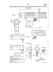
Actually not really a separate part as it is part of the telescoping recoil spring assembly but since it is such an important part of the MP40 operation I still want to mention something about it. The firing pin underwent a modification during the war; apparently it was initially designed too long. In the “Heeres Verordnungsblatt” of November 16th 1942 it was ordered that the projecting pin (from the bolt face) be shortened from 1.4 mm to 1.3 mm.
Translation of the PDF:
704 Firing pin fore end of the MP40
The firing pin front end of the mp40 has to be shortened with 0.1 mm so that the total length of the firing pin fromt end is 1.3 mm. The modification has to be done on all MP38’s and MP40’s by the “Truppenwaffenmeister”. Special modification manuals are not published.
D.R.H. (Ch H Rüst u. BdE, 10.11.42 -72b- In 2 (IId).
Since my technical knowledge is limited I asked Rich R. to explain what problems may arise with a firing pin that is too long:
1. Ignition of the primer sooner than desired as the shell casing of the 9mm round is more prone to rupture upon detonation of the charge when the shell is not more fully placed within the confines of the chamber, especially if there were to be any friction on the brass casing from minor flecks of debris.
2. A reliable cycling rate is important to the operation of the machine pistol. The 9mm round detonating before the cartridge is optimally placed may mean less time for the powder to burn effectively before beginning the recoil cycle, thereby adversely influencing the recoil impulse of the expended cartridge and possibly causing a jam..
3. Some military primers may be hardened more than others, with a firing pin too long, there may be the risk of “pierced primers.”
4. There is the possibility that a longer firing pin may be more brittle than the shorter firing pin. Remember, with the firing pin detonating before the round is fully seated, the firing pin is minutely hitting the primer at an angle and thereby causing stress on the tip of the firing pin.
.jpg)
Since I’m so keen on mentioning the different modifications of every part you could say that there are 3 versions of the firing pin. One “unchanged” (original design) 1.4 mm long firing pin, an adapted version by the “Waffenmeisters” (All MP38’s and MP40 had to be adapted by the Waffenmeister) and the last production version of 1.3 mm. Since the differences are so small it’s almost impossible to measure it with the average garage tools and not at all with the eye.
I’m not sure how serious this order was taken. After all the Waffenmeister gauges were not made to measure if the firing pin was too long. It was made to measure the deterioration of a firing pin (taking the 1.3 mm as a reference). I have not I have not heard of a gauge that would measure this “problem”. If anybody has more Information about this topic then please e-mail me at info@mp40.nl.